Advanced Alignment in Grasshopper3D
by Clark Cheng
This project demonstrates techniques for aligning objects from a base geometry. It was developed during my time at UAP as part of the Milken Tree of Generations project.
The focus was on exploring efficient methods to sort elements by area and determine optimal routes for alignment using only mesh references supplied by the client. By reconstructing the NURBS base from these references, the workflow highlighted how computational design can streamline complex fabrication alignment challenges.
The process combined precision data handling, parametric logic, and geometric intuition to achieve clean, repeatable transformations across multiple scales. Each iteration refined both the algorithm and the understanding of how the meshes interacted with their source forms.
This approach not only ensured higher accuracy but also revealed a robust framework for future automation in aligning irregular geometries—balancing digital efficiency with craftsmanship in the physical outcome.
Ultimately, the project became a case study in bridging client-provided mesh data with internal parametric workflows—an elegant dance between art, math, and manufacturing.
This full Grasshopper script outlines the complete process for aligning geometry, from data extraction to final placement.
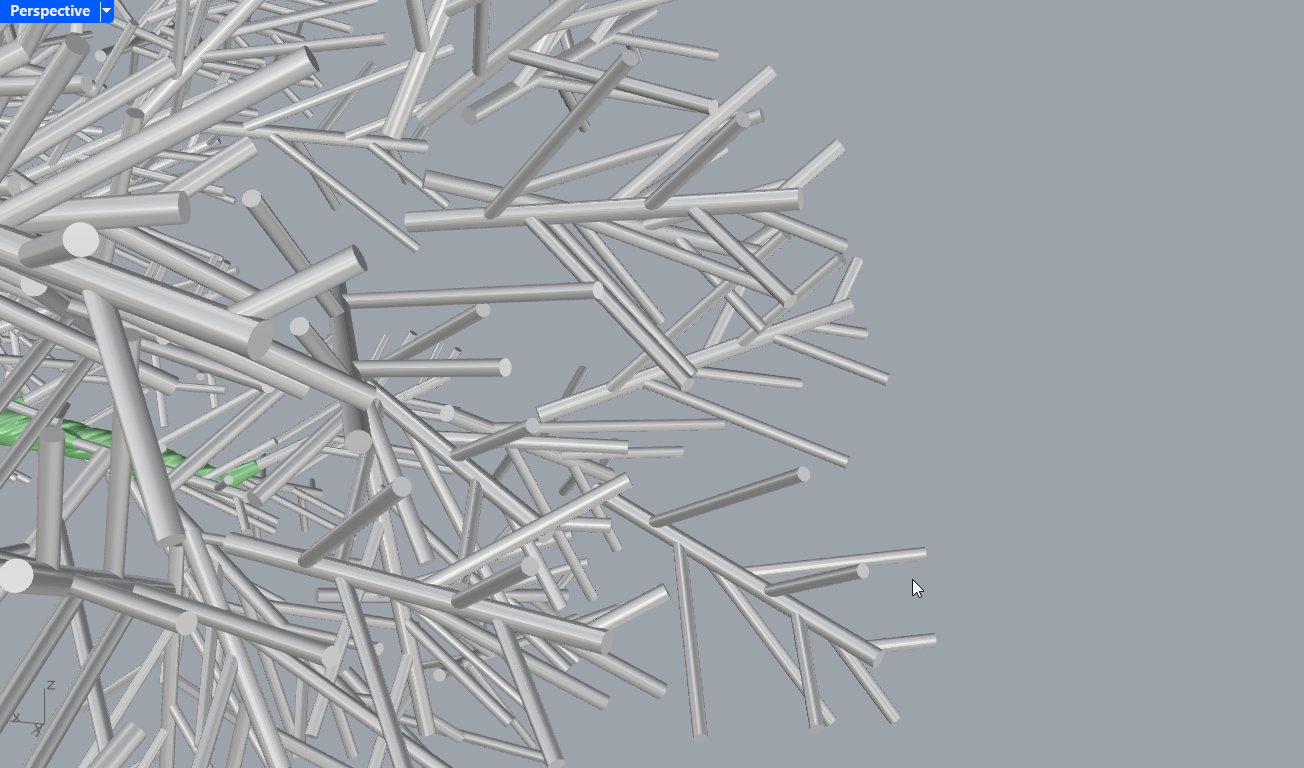
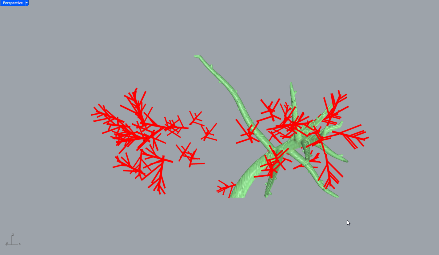
An overview of the assembled structure in Rhino, showing the aligned components across the main geometry branches.
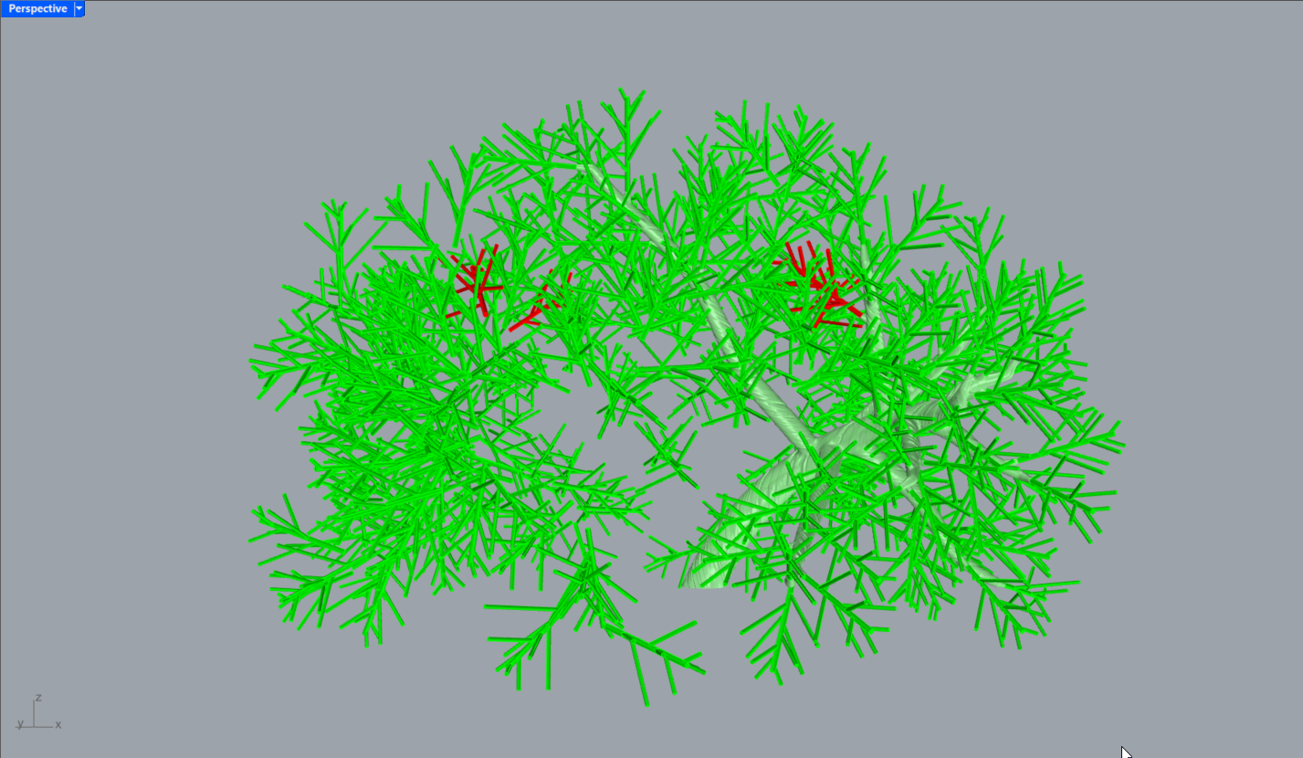
Initial reference geometry setup — showing the first alignment vectors and extracted base branches.
Secondary alignment visualization, highlighting orientation adjustments between generated NURBS and the provided mesh references.
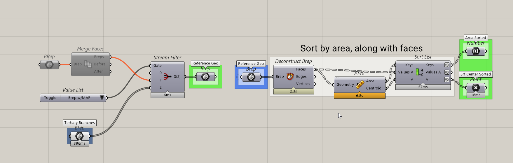
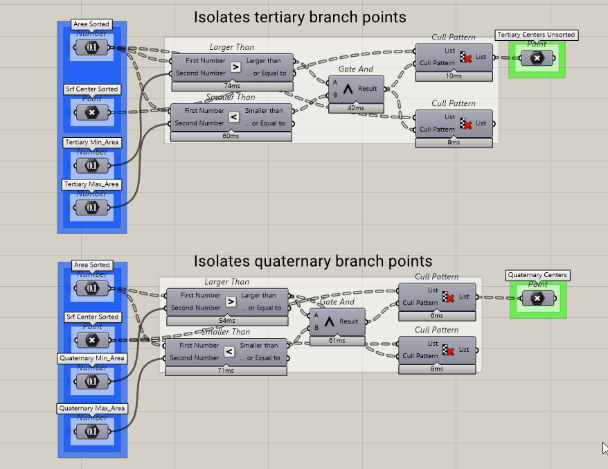
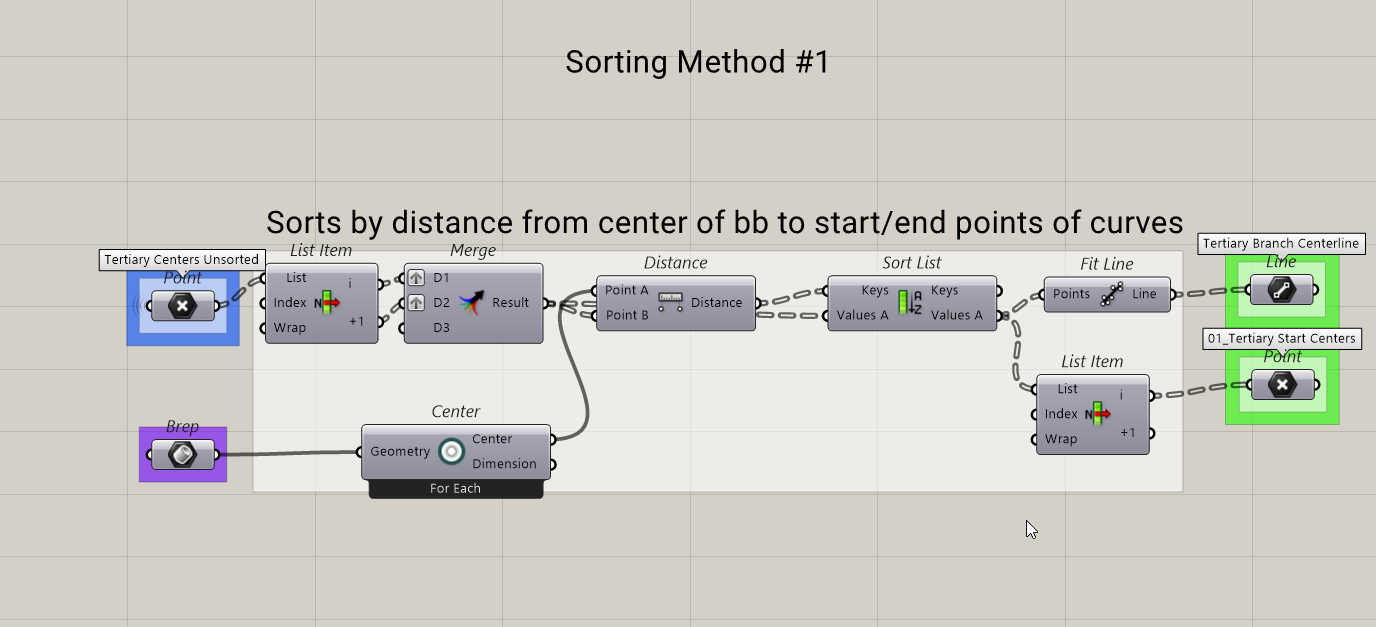
Step 1: Begin by sorting elements by area to isolate key mesh components and simplify the input data structure.
Step 2: Apply alignment logic to translate, rotate, and match components along the reference geometry path.
Step 3: Use modular clusters to generate repeatable transformation definitions and control object behavior parametrically.
Step 4: Integrate results into the global model and test tolerance values for accurate placement and connection points.
Intermediate check showing aligned branch sets within the main assembly.
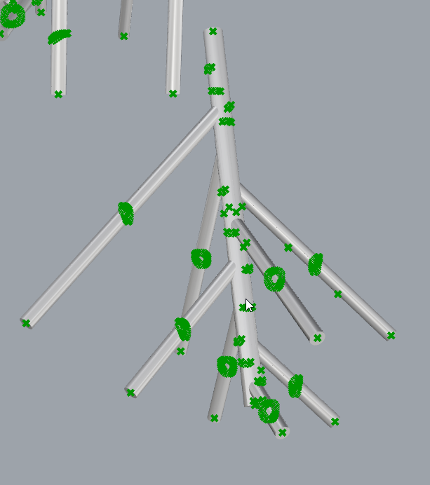
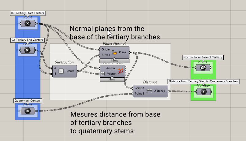
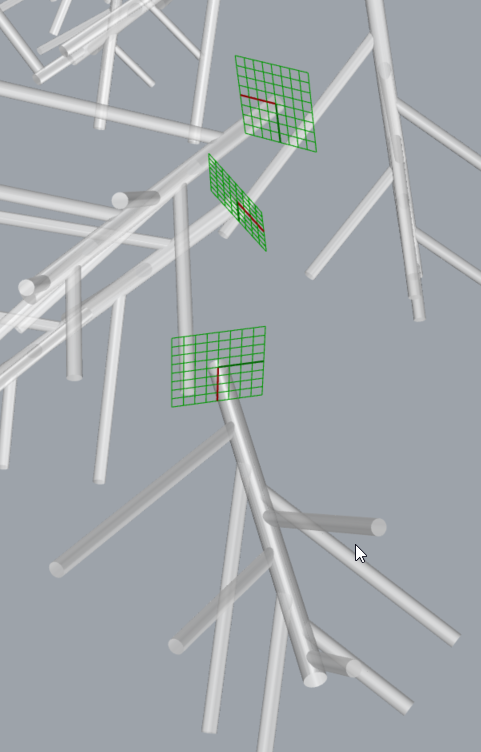
Close-up of refined node connections and adjusted normals for improved precision.
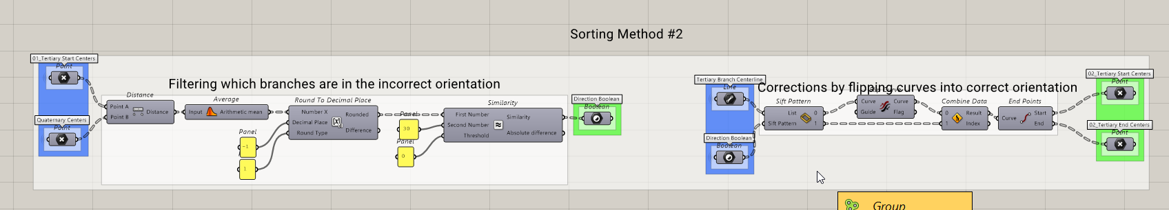
Step 5: Validate orientation consistency and ensure smooth directional flow across branches.
Step 6: Final data bake and preparation for export to fabrication workflows.


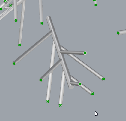
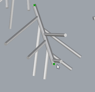
Collection of close-up views illustrating mesh alignment, branching accuracy, and node connectivity validation.
Orientation verification — ensures all branches follow their intended growth directions and maintain correct vector relationships.
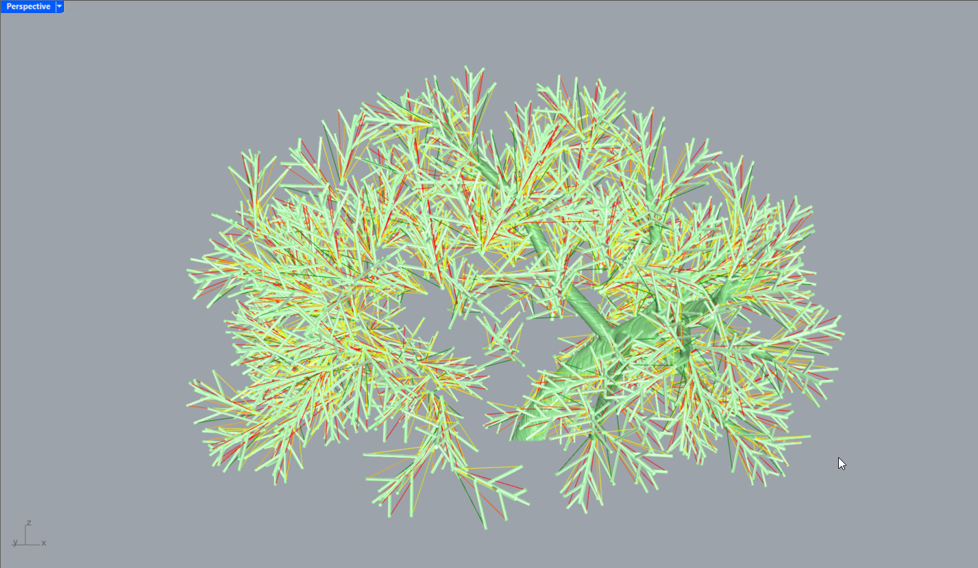
Color-coded visualization distinguishing unique geometries within the aligned set, identifying duplicates and outliers.
The final alignment result — all elements positioned and oriented precisely according to the base geometry structure.